The Short Answer: Select the Environment, Product Form, and Fabrication Route Together
A stainless steel cable tray does not succeed merely because a drawing says “SUS 304” or “SUS 316L.” Its service life is the result of a chain of decisions: the actual atmosphere around the tray, the geometry that can retain moisture, the grade and condition of the incoming sheet or coil, thickness and dimensional tolerances, punching and bending practice, welding heat input, post-fabrication cleaning, support spacing, installation quality, and future maintenance. If one link is weak, an expensive grade can still underperform.
For dry, controlled indoor spaces, 304 or 304L often provides an effective balance of availability, formability, appearance, and corrosion resistance. Where chloride deposition, salt spray, aggressive washdown chemicals, condensation, or persistent crevices are credible, 316L is frequently the safer starting point because molybdenum improves resistance to chloride-induced pitting and crevice corrosion. “Frequently” is important: 316L is not immune to seawater, warm chlorides, deposits, or poor design. Some severe services require a more corrosion-resistant alloy, a different system architecture, or a site-specific corrosion study.
The procurement specification should therefore describe the environment and the finished-system requirement before naming the grade. It should also define the applicable material standard, surface finish, thickness tolerance, flatness, width, edge and burr limits, mechanical properties, certificate requirements, protective film, traceability, and the tests expected from the finished cable tray manufacturer. Genn-Hann supplies and processes stainless steel coil, strip, and sheet for fabricators. We do not manufacture or certify finished cable tray systems. That boundary is essential: material conformity supports system performance, but it does not replace structural testing, electrical evaluation, or installation engineering.
Why Cable Management Material Is an Infrastructure Decision
Cable trays and ladders are rarely the most visible equipment in a project, yet they carry the conductors that connect switchgear, drives, instruments, servers, safety systems, communication networks, and process controls. A local failure can interrupt much more valuable equipment. Corroded rungs can damage cable jackets; loose covers can become hazards; overloaded spans can deflect; contaminated weld zones can rust early; and inaccessible layouts can turn a minor cable addition into a shutdown task.
The material decision also affects construction. Stainless steel can reduce dependence on sacrificial coatings and repeated repainting, but it requires disciplined segregation from carbon steel, suitable tooling, controlled welding, and appropriate cleaning. A low first price is therefore not the same as a low installed cost. Conversely, specifying 316L everywhere without understanding the exposure can consume budget without reducing the dominant risk. In a conditioned electrical room, poor support spacing or unverified load capacity may matter more than the difference between 304 and 316L.
Experienced teams treat the tray as a system rather than a length of folded metal. They ask how cables enter and exit, where water drains, whether dissimilar metals touch, how expansion is managed, how bonding is maintained across joints, and whether maintenance crews can inspect concealed surfaces. Material selection then becomes part of a coordinated reliability decision rather than a purchasing shortcut.
Start with the Standard and the Responsibility Boundary
IEC 61537:2023 specifies requirements and tests for cable tray and cable ladder systems used to support and accommodate cables and, in some cases, other electrical equipment. Its scope is the finished system, including relevant support devices and safe working load testing. The standard explicitly distinguishes cable tray and ladder systems from conduit, trunking, and ducting. That distinction matters because a solid-bottom tray is not automatically an enclosed raceway, and compliance language should match the product actually supplied.
North American projects may also refer to NEMA VE 1 for metal cable tray construction and performance, NEMA VE 2 for installation guidance, and the locally adopted electrical code. The edition and jurisdiction must be stated. A reference copied from an old tender may no longer be current, and an international project may combine standards that classify loads or corrosion differently. The engineer of record should resolve conflicts rather than expecting the raw-material supplier to infer the governing hierarchy.
ASTM A240/A240M is a common material specification for chromium and chromium-nickel stainless steel plate, sheet, and strip used in general applications. Other national or regional standards may be specified instead. A grade name alone is insufficient because equivalent designations can have differences in permitted chemistry, product form, or delivery condition. The purchase order should state the complete standard and edition required by the project.
The responsibilities normally divide as follows. The owner or engineer defines service conditions, codes, design life, electrical requirements, loads, and inspection expectations. The cable tray manufacturer designs the profile, joints, fittings, covers, and supports; validates safe working load and system performance; and supplies installation instructions. The stainless steel service center supplies material meeting the agreed standard and order requirements, with the requested processing and documentation. The installer follows the approved layout and maintains system continuity, spacing, supports, and workmanship. Blurring these roles produces vague claims and unowned risks.
Decode the Main Cable Tray and Ladder Geometries
Cable Ladder
A cable ladder uses two longitudinal side rails connected by transverse rungs. It is common for power cables and long industrial routes because it offers ventilation, easy cable access, and a clear path for fastening cables. The design capacity depends on the rail profile, rung geometry, connection method, support span, steel thickness, mechanical properties, and fittings—not on grade name alone.
Outdoor ladders expose many edges, joints, fasteners, and horizontal surfaces to deposits. Rungs welded to side rails create heat-affected zones that must be cleaned correctly. In coastal or chloride-bearing locations, 316L is often selected, but drainage and deposit removal remain essential. An oversized 316L ladder that traps saline water may perform worse than a well-drained system made from an appropriately selected alloy and maintained on schedule.
Ventilated or Perforated Cable Tray
Ventilated trays use formed sidewalls and a base with openings. They balance support, cable protection, drainage, and air circulation. Hole pattern, web width, embossing, and sidewall geometry influence stiffness. The fabrication route can involve decoiling, leveling, roll forming, stamping, bending, welding, and cutting, so strip flatness and consistent thickness can affect both productivity and the final product.
Punching does not become corrosion-resistant simply because the substrate is stainless. Tool clearance, punch condition, lubrication, edge rollover, fracture zone, burr height, and subsequent cleaning determine edge quality. Stainless steel can reform a chromium-rich passive film in a clean, oxygenated environment, but embedded iron, heat tint, tightly packed debris, or persistent chloride deposits can defeat that advantage. The purchaser should specify acceptable burrs and the manufacturer should validate the process for the actual thickness and temper.
Solid-Bottom Tray
Solid-bottom tray provides continuous mechanical support and can help protect cables from falling debris or localized external contact. It can also retain water, cleaning solution, dust, or chemicals unless drainage and slope are deliberately managed. Covers add protection but create additional crevices and can restrict heat dissipation. Cable ampacity and fill must be evaluated under the applicable electrical rules and the manufacturer’s instructions.
A solid metal bottom should not be marketed as guaranteed electromagnetic shielding. Effective EMC control depends on enclosure continuity, joint impedance, bonding, cover design, cable entry details, frequency, and tested system behavior. When EMC is a project requirement, the engineer should specify measurable performance and a complete bonding concept instead of relying on the visual presence of metal.
Wire Mesh Tray
Wire mesh tray is frequently used for telecommunications, controls, and data-center pathways because it can be light, visible, and easy to modify on site. Its performance depends on wire diameter, grid geometry, weld quality, fittings, supports, cut-edge treatment, and installation practice. Field cuts can leave sharp ends or contaminated surfaces, so approved cutting tools and protective accessories are important.
Selecting 316L wire may reduce corrosion risk in chloride-bearing locations, but the welds and field-modified areas still deserve inspection. The low carbon content of 316L reduces susceptibility to sensitization during welding; it does not guarantee that every weld is free of oxidation, contamination, or local attack.
Channel and Single-Rail Systems
Channel trays serve smaller cable quantities or branch routes, while single-rail systems may be chosen for access and flexibility. These lighter-looking products still require verified load data and compatible fittings. Concentrated loads, vertical runs, transitions, and cable pulling forces can govern even when the steady cable weight appears modest.
Structural Performance: Grade Is Only One Variable
The safe working load of a cable tray system cannot be calculated from “304” or “316L” alone. Austenitic grades have broadly similar elastic modulus, while yield strength varies with grade, thickness, delivery condition, cold work, and product standard. Profile geometry often has a greater effect on stiffness than a small difference in nominal grade strength. Side-rail height, return flanges, corrugations, rung spacing, joint location, and support span all matter.
Project teams should define distributed cable load, future reserve, concentrated maintenance or installation loads if applicable, span, support arrangement, vertical orientation, environmental loads, and required safety factors. Wind, snow, ice, seismic action, vessel motion, vibration, thermal movement, and accidental impact may be relevant in some locations but should not be added as generic marketing claims. Each must be evaluated for the project.
Deflection limits also deserve attention. A tray can remain below material yield yet deflect enough to compromise appearance, drainage, clearances, or cable support. Joint positions relative to supports may change the response. Fittings such as elbows, tees, reducers, and risers introduce load paths that differ from straight runs. The finished-system manufacturer should publish tested configurations and installation limitations.
A material supplier can help control variables that influence repeatability: thickness tolerance, mechanical property range, flatness, camber, coil set, and width. We cannot convert those controls into a system load rating without the manufacturer’s design and testing. Procurement documents should keep the material acceptance criteria and finished-system performance criteria connected but distinct.
Corrosion Begins with the Microenvironment, Not the Postal Address
“Indoor,” “outdoor,” “coastal,” and “chemical plant” are useful screening labels, not complete exposure descriptions. A tray inside a building can face condensation, chlorine-bearing cleaners, battery-room contaminants, process vapors, or wet insulation. An outdoor tray in a clean rural location may dry quickly and remain relatively benign. A tray several kilometers from the sea can still collect salt carried by wind, while a sheltered coastal component may retain deposits longer than one washed by rain.
The most useful questions concern time of wetness, chloride deposition, temperature, pH, oxidizing conditions, cleaning chemistry, crevices, deposits, drainage, and access for washing. Warm chloride solutions are more aggressive than occasional cool exposure. Evaporation can concentrate salts far beyond their concentration in incoming water. Gaskets, overlapping joints, labels, cable ties, and packed dust can create local crevices where oxygen is depleted and corrosion becomes more severe than on an open surface.
ISO 12944 corrosivity categories are sometimes used in project conversations to describe atmospheric severity. The series is primarily directed to protective paint systems for steel structures. Its environmental language may help organize site data, but it should not be treated as a direct stainless steel service-life calculator. Stainless grade selection needs stainless-specific evidence, including local experience, testing where appropriate, and review of the actual microenvironment.
304 and 304L: The Practical Baseline
Type 304 is the familiar chromium-nickel austenitic stainless steel often described by the shorthand “18-8.” That shorthand is not a purchase specification. Chemical composition must conform to the selected material standard and be confirmed by the relevant certificate or test plan. For cable tray fabrication, 304 offers strong availability, good formability, weldability, and a cleanable surface.
304 is commonly suitable for dry commercial interiors, conditioned data halls, many indoor industrial areas, and applications where chloride contamination is low and surfaces can dry. It can also work in more demanding settings when design and maintenance prevent deposits. The correct conclusion is not that 304 is “indoor only,” but that its margin against chloride pitting is lower than that of 316-series material.
304L limits carbon compared with 304 and is often preferred when extensive welding or demanding fabrication makes resistance to weld sensitization important. Modern production practices mean many products meet dual 304/304L chemistry and mechanical requirements, but dual certification must be documented rather than assumed. Low carbon does not make 304L equivalent to 316L in chloride resistance because it does not add molybdenum.
Typical warning signs for 304 include tea staining or localized rust near the coast, pitting beneath salt deposits, attack around poorly cleaned weld heat tint, and contamination from carbon-steel tooling. Some discoloration is superficial and removable; deep pits, section loss, cracked welds, or damaged cable-contact surfaces are different. Inspection criteria should distinguish appearance from structural or functional damage.
316 and 316L: More Chloride Resistance, Not Immunity
Type 316 includes molybdenum, which improves resistance to pitting and crevice corrosion compared with 304 in many chloride-bearing environments. Type 316L provides the lower-carbon variant, often favored for welded assemblies. It is a common choice for coastal infrastructure, wastewater facilities, chemical processing areas, aggressive washdown zones, and selected food or pharmaceutical utilities.
The upgrade has limits. 316L can pit or develop crevice corrosion in warm, concentrated, stagnant chloride solutions. Marine splash, sheltered salt accumulation, bleach exposure, hydrochloric acid contamination, and high-temperature process environments may exceed its capability. The grade should never be described as “marine proof” without conditions. In severe service, duplex or higher-alloy stainless steels, nonmetallic systems, coatings, cathodic protection, or redesigned drainage may be evaluated by a corrosion specialist and the system manufacturer.
The “L” suffix reduces carbon to limit chromium carbide precipitation and the associated risk of intergranular corrosion after welding. It does not eliminate weld-quality risks. Excessive heat input, poor shielding, heat tint, rough grinding, iron contamination, or incomplete pickling can still create vulnerable areas. A good specification addresses both alloy choice and fabrication control.
When Other Stainless Grades Enter the Discussion
Ferritic grades can offer cost and thermal-expansion advantages in selected applications, but they are not automatic substitutes for 304. Formability, weld procedure, toughness, surface appearance, availability, and corrosion behavior must be reviewed against the actual design. A lower nickel content does not by itself make a grade economically superior once tooling changes, qualification, and supply consistency are included.
Duplex stainless steels combine ferritic and austenitic structures and can offer higher strength and improved resistance to chloride stress corrosion cracking and localized corrosion. Their higher strength may permit redesign, but simply substituting duplex into a profile developed for 304 is not a complete engineering exercise. Forming loads, springback, welding consumables, heat input, phase balance, and availability require attention.
For most cable tray programs, a disciplined choice between 304/304L and 316/316L covers the mainstream. Other alloys become valuable when a quantified exposure or design objective justifies the additional qualification work.
Product Form and Supply Condition Affect Fabrication
Cable tray factories often purchase slit coil for continuous roll forming or stamping and sheet for batch fabrication, fittings, covers, and custom components. The best form depends on volume, line configuration, part mix, handling equipment, and traceability strategy. Coil supports high productivity, but incoming coil shape must be compatible with the straightener and roll-forming line. Sheet simplifies certain operations but adds handling and blanking decisions.
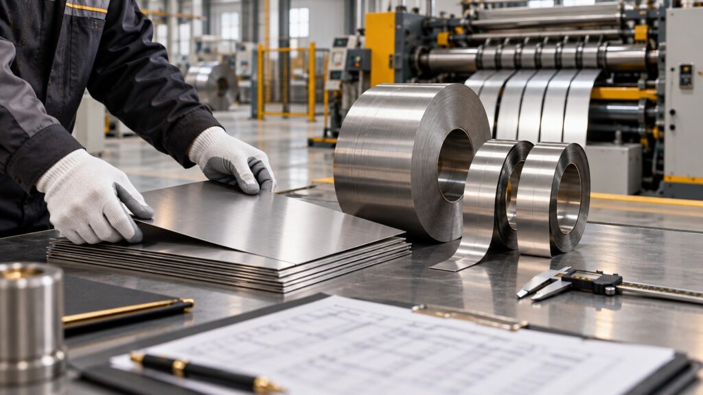
For stainless steel coil and strip, specify alloy, standard, finish, thickness and tolerance, width and tolerance, coil inside diameter, maximum outside diameter or weight, edge condition, mechanical properties, flatness or shape expectations, paper interleaving if required, and protective film. A “same nominal thickness” order can behave differently if tolerance ranges or mechanical conditions differ.
Precision stainless steel coil slitting (/stainless-steel-coil-slitting/) matters because width consistency affects roll-form registration, flange dimensions, and scrap. Edge wave, camber, telescoping, and burr orientation can disrupt feeding. For sheet-based fabrication, stainless steel sheet cutting (/stainless-steel-sheet-cutting/) requirements should consider squareness, cut edge, flatness, and surface protection.
Thickness Tolerance Is a Commercial and Structural Issue
Nominal thickness appears simple until drawings, mill tolerances, finished part measurements, and load tests disagree. A design based on nominal thickness must account for the permitted negative tolerance in the governing material standard and the manufacturer’s production controls. The finished-system test program should represent the product actually sold, not an unusually favorable prototype.
Overly tight tolerances raise cost and can reduce sourcing flexibility. Overly broad tolerances may create forming variation, weight uncertainty, and inconsistent structural performance. The correct range comes from a capability study connecting incoming material, tooling, profile dimensions, weld quality, and system tests.
Procurement teams should also clarify where and how thickness will be measured. Surface texture, coatings or films, curved profiles, and instrument calibration can influence readings. Acceptance disputes are less likely when the order defines the material basis, sample plan, equipment, and governing standard before shipment.
Flatness, Camber, Coil Set, and Surface Protection
Flatness is not just an appearance requirement. Poor shape can cause misfeeds, hole-position variation, twisted profiles, uneven joints, and cover fit problems. Coil set and crossbow interact with line tension and leveling. Camber can shift a slit strip laterally across long runs. These conditions should be discussed using measurable criteria tied to the process, not subjective phrases such as “must be perfectly flat.”
Protective film can reduce scratching during forming, transport, and assembly, but the film must match the forming temperature, lubricant, storage period, and removal schedule. Film left outdoors too long can degrade or leave adhesive. Trapped moisture or chloride beneath damaged film can create staining. The fabricator should validate film performance and remove it according to supplier instructions.
Surface finish influences appearance, cleanability, friction, and visibility of handling marks. A standard mill finish is not the same as a polished architectural finish. The stainless steel surface finish guide (/stainless-steel-surface-finish/) should be used to align terminology, samples, and acceptance criteria. A photograph alone is not a reliable finish specification because lighting and camera processing change appearance.
Punching, Cutting, and Burr Control
Punching hundreds or thousands of ventilation holes places repeatable demands on the material and tooling. Tool clearance should be selected for stainless steel grade, thickness, hardness, and desired edge. Too little clearance increases force and wear; too much can enlarge the fracture zone and burr. Dull tools raise heat, distortion, and burr height. Lubricants must be compatible with later cleaning and welding.
The corrosion concern is not that every punched edge is defective. Stainless steel naturally repassivates when clean and exposed to oxygen. The risk arises when cutting introduces embedded iron, smeared material, heavy burrs, trapped lubricant, or crevices that retain contaminants. Deburring methods must not spread carbon-steel particles. Abrasives and brushes should be dedicated to stainless work.
Laser cutting provides flexibility for fittings and low-volume parts, but heat tint and dross require control. Plasma cutting may require more edge finishing depending on process and quality target. Waterjet avoids a broad thermal zone but brings its own edge, contamination, and productivity considerations. The correct method depends on geometry, volume, downstream forming, and required surface condition.
Bending and Roll Forming: Respect Springback and Directionality
Austenitic stainless steels work harden during forming. Springback, tool loads, and minimum bend radius depend on grade, thickness, temper, bend direction, and geometry. Sharp inside radii can increase strain and risk cracking, particularly where punched holes or sheared edges lie close to the bend. Design reviews should consider the actual blank layout rather than applying a generic radius rule.
Roll-forming lines require stable strip width, shape, and mechanical properties. Changes in coil source or condition can shift springback and final dimensions even when grade and nominal thickness remain unchanged. First-article checks after material changes are a practical control. Monitoring flange height, rail straightness, hole location, twist, and joining fit produces more useful evidence than relying only on incoming chemistry.
Tooling used for carbon steel should not contact stainless unless it is thoroughly controlled to prevent contamination. Dedicated storage racks, lifting equipment contact surfaces, and work tables are part of the same discipline. Many early “stainless rust” complaints trace back to fabrication or handling contamination rather than incorrect alloy chemistry.
Welding, Heat Tint, Pickling, and Passivation
Welding changes the local surface and microstructure. A sound procedure controls joint preparation, filler selection, shielding, heat input, distortion, and cleaning. Dark heat tint indicates oxide formation and chromium depletion immediately beneath the oxide; it can reduce local corrosion resistance. The required remediation depends on exposure and specification, but ignoring heavily oxidized welds in a chloride environment is poor practice.
Pickling removes heat tint and a thin affected surface layer. Passivation treatments help remove free iron and promote a clean passive surface, but the terms are not interchangeable and chemical handling requires qualified procedures. Mechanical cleaning alone can leave a rough or contaminated surface if tools are inappropriate. Fabricators should follow recognized guidance, chemical supplier instructions, and environmental and worker-safety controls.
After treatment, rinse water quality and complete drying matter. Residual acid or chloride-containing water can create new staining. Acceptance can include visual inspection and, where justified, tests for free iron or surface condition. No single field test proves long-term corrosion resistance; test methods should be selected for the specification and interpreted by competent personnel.
Fasteners, Joints, and Dissimilar-Metal Contact
A tray system includes bolts, splice plates, clips, supports, anchors, covers, and bonding components. Using a stainless tray with incompatible fasteners can create local corrosion, staining, loss of joint integrity, or maintenance difficulty. Fastener grade, strength class, galling risk, washer arrangement, torque, and locking method should be specified as a system.
Stainless fasteners can gall during tightening. Clean threads, appropriate lubricants approved for the service, controlled installation speed, and specified torque help. Substituting fasteners in the field can compromise both mechanical performance and electrical bonding. Replacement parts should match the manufacturer’s approved configuration.
Dissimilar-metal contact does not always cause immediate failure, but galvanic risk depends on the metal pair, area ratio, electrolyte, and continuity. A large stainless surface connected to a small, wet, less-noble fastener can accelerate attack of the fastener. Isolation materials can reduce galvanic current but may affect bonding or fire performance. The engineer should coordinate corrosion isolation with electrical continuity rather than solving one issue by creating another.
Electrical Bonding, Grounding, and EMC Are System Functions
Metal cable trays may participate in bonding or protective-earth arrangements only when allowed by the governing code, the system is evaluated for that function, and installation maintains continuity. Material conductivity, cross-sectional area, joints, splice hardware, coatings, corrosion, and fault-current requirements all influence performance. A stainless steel label alone does not certify a tray as a protective conductor.
Every expansion joint, removable section, hinge, or field modification is a potential continuity issue. Bonding jumpers may be required by the design or manufacturer. Testing and inspection should follow the project’s electrical quality plan. Corrosion products, loose hardware, paint overspray, and nonconductive isolators can increase connection resistance over time.
EMC performance is likewise system-specific. Cable segregation, routing, bonding topology, covers, joint design, and termination details may matter more than bulk alloy choice. When electromagnetic compatibility is critical, involve the electrical or EMC engineer early and require evidence for the complete installed configuration.
Application Guidance by Industry
Data Centers and Telecommunications
Conditioned data halls often present a relatively mild atmospheric environment, making 304 a common candidate. However, cooling-water leaks, humid air near exterior intakes, battery areas, rooftop routes, and generator yards can create different zones within one campus. A single blanket grade can be convenient, but zoning may optimize cost if traceability and installation controls prevent mix-ups.
Wire mesh and ladder systems support frequent changes. Smooth edges, bend-radius management, accessible routing, and reliable bonding can be more important than a premium finish. Capacity planning should include realistic future cable additions without encouraging uncontrolled overfilling.
Power Generation and Substations
Power facilities combine heavy cables, long routes, outdoor exposure, heat, vibration sources, chemicals, and critical availability. The environmental survey should distinguish turbine halls, cable tunnels, cooling-water areas, chemical dosing zones, flue-gas treatment, coastal switchyards, and control rooms. 316L may be appropriate in selected wet or chloride-bearing zones while 304 may serve controlled interiors.
Supports and seismic requirements deserve particular attention. A corrosion-resistant tray that detaches from an inadequately designed support is not a reliable system. Cable pulling, short-circuit forces where relevant, and fire-stopping interfaces should be addressed by the responsible disciplines.
Oil, Gas, Petrochemical, and Chemical Processing
These sites can expose tray systems to salt, sulfur compounds, acids, alkalis, solvents, process deposits, and hazardous-area requirements. “Chemical plant” is too broad for alloy selection. Obtain chemical identity, concentration, temperature, frequency, condensation behavior, and cleaning methods. A brief splash that is promptly rinsed differs from continuous vapor condensation beneath a cover.
316L is common but may be insufficient for particular acids, halides, or temperatures. Materials specialists should review severe cases. Fireproofing, insulation, coatings, and supports can create crevices or obscure inspection. The maintenance plan must be compatible with access restrictions and hazardous-area procedures.
Marine, Offshore, and Coastal Infrastructure
Salt deposition, wet-dry cycling, crevices, and sheltered surfaces make coastal service demanding. Distance from shore alone is not a reliable metric. Prevailing wind, elevation, rain washing, orientation, and nearby cooling towers affect chloride load. 316L generally offers a better margin than 304, but regular fresh-water cleaning and drainage may still be necessary to control tea staining and localized attack.
Offshore splash and process areas can exceed 316L capability. The system owner should define zones and use documented site experience or testing. Fasteners, supports, clamps, labels, and cable armor must be included in the corrosion review; upgrading only the tray can move the failure to a less visible component.
Food, Beverage, and Pharmaceutical Facilities
Stainless steel is valued for cleanability, but cable trays are generally utility components rather than food-contact surfaces. Hygienic requirements should be based on location, cleaning regime, contamination control, and owner standards. It is inaccurate to claim that GMP or HACCP automatically mandates one universal surface roughness for every tray.
Frequent washdown with chlorinated or acidic cleaners can be more aggressive than the ambient room. 316L may be justified, but cleaner concentration, dwell time, temperature, rinsing, and drying are decisive. Open, drainable designs may be easier to inspect than enclosed trays that trap residue.
Wastewater and Water Treatment
Wastewater plants combine humidity, condensation, chlorides, hydrogen sulfide in some areas, treatment chemicals, and outdoor exposure. Headworks, chemical rooms, covered basins, sludge processing, and administration spaces are different microenvironments. Grade zoning and maintainable routing can provide better value than a single undifferentiated specification.
Tunnels, Transit, and Underground Infrastructure
Tunnels can retain humidity, brake or road dust, deicing salts, wash water, and pollutants. Access for repair may be costly, so lifecycle planning is important. Fire, smoke, vibration, anchorage, and evacuation requirements are system issues beyond raw-material selection. The tray manufacturer and engineer must coordinate alloy, structural design, fasteners, and installation details.
Renewable Energy and Industrial Outdoor Routes
Solar, wind, battery, and process electrification projects often place cable routes outdoors for decades. UV exposure affects nonmetallic accessories and protective films, while condensation and salt can affect metal components. Stainless steel can reduce coating-maintenance demands, but drainage, expansion, grounding, and compatible supports remain essential.
Counterexamples That Expose Weak Specifications
Counterexample 1: “316L Means No Maintenance”
A covered 316L tray near a cooling tower collects chloride-rich drift. The cover prevents rain washing, and warm surfaces repeatedly dry the droplets, concentrating salts. Pitting appears at lap joints. The alloy upgrade delayed corrosion but did not remove the deposit mechanism. Better drainage, cleaning access, drift control, and inspection were also required.
Counterexample 2: “304 Is Always Unsuitable Outdoors”
A 304 ladder in a clean inland environment remains dry, receives rain washing, and is inspected periodically. It performs satisfactorily for years. Replacing it with 316L would not correct the project’s actual concern: under-designed supports in a high-wind zone. Environment-specific evidence prevents money from being spent on the wrong risk.
Counterexample 3: “The Mill Certificate Proves the Finished Tray”
The incoming coil meets ASTM A240/A240M, but the fabricator uses worn punches, carbon-steel brushes, and an uncontrolled weld-cleaning process. The finished parts show burrs, embedded iron, and heat tint. The certificate proves the supplied material’s reported properties; it does not certify fabrication quality or IEC 61537 performance.
Counterexample 4: “Solid Bottom Automatically Solves EMC”
A project selects a solid-bottom tray expecting signal protection, but joints are discontinuous, the cover is loosely fitted, and cable entries are unmanaged. Interference remains. A complete EMC design with verified bonding, segregation, and termination was needed.
Counterexample 5: “Thicker Material Guarantees Higher Capacity”
A thicker strip is substituted without rechecking forming. Increased springback changes rail geometry and joint fit. The resulting system does not reproduce the tested configuration. Thickness can improve capacity only when the profile, joints, supports, and production controls remain within the validated design.
Counterexample 6: “Low Carbon Eliminates Weld Corrosion”
A 316L ladder is welded with excessive heat and insufficient shielding, leaving heavy oxide. It is installed without pickling or appropriate cleaning in a saline area. Local corrosion begins at welds. Low carbon reduced sensitization risk but did not correct poor surface condition.
Lifecycle Cost: Compare Scenarios, Not Slogans
Total cost of ownership includes raw material, yield, forming speed, tooling, welding and cleaning, fasteners, support design, freight, installation, inspection, washing, repairs, access, replacement, and downtime. 316L may have a higher purchase price than 304 because of alloy content and market conditions, but no responsible supplier should promise a fixed percentage premium or a guaranteed payback period without current quotations and project data.
Build at least three scenarios: a baseline grade with expected maintenance, an upgraded grade with revised maintenance, and a design change that reduces moisture or deposits. Estimate inspection intervals, cleaning access, probability and consequence of local repair, and replacement disruption. Use ranges rather than false precision. For a remote offshore module or live data center, avoided access and downtime may dominate. For an accessible dry warehouse, the premium may not be justified.
Lifecycle analysis should also consider supply continuity and fabrication qualification. A technically superior alloy that is unavailable in the required width or cannot be processed consistently may create schedule and quality risk. Early discussion with the material processor and tray manufacturer helps align design ambition with a stable supply route.
How to Write a Procurement Specification That Can Be Enforced
Begin with service conditions: installation zone, indoor or outdoor exposure, temperature range, humidity or condensation, chloride or chemical sources, cleaning agents, design life, inspection access, and criticality. Then state the governing cable tray system standard, edition, electrical code, load class or tested safe working load, support span, deflection requirement, and any seismic, wind, fire, or bonding requirements.
For material, state the full grade and standard, product form, finish, thickness and tolerance, width and tolerance, mechanical property requirements, edge condition, flatness or shape criteria, surface acceptance, protective film, and traceability. If welded, define approved procedures, heat-tint acceptance, and post-weld cleaning. If the order requires an EN 10204 type 3.1 inspection certificate or another certificate, state that requirement before quotation. Availability must be confirmed; it should not be assumed for every stock item.
For the finished system, require manufacturer drawings, load-test evidence, fitting and support compatibility, installation instructions, fastener specification, bonding provisions, labeling, and inspection records. Define the sample plan and acceptance process. Avoid clauses such as “marine grade,” “highest quality,” or “zero rust” unless they are replaced with measurable requirements.
RFQ Checklist for Stainless Steel Coil, Strip, or Sheet
Provide the following information when requesting a quotation from a stainless steel supplier or service center:
- Grade and complete material standard, including edition if contractually required.
- Coil, slit strip, sheet, or blank dimensions.
- Thickness, width, length, and tolerances.
- Surface finish and visual acceptance criteria.
- Edge condition and maximum burr where applicable.
- Coil inside diameter, outside diameter, and weight limits.
- Flatness, camber, coil set, or special shape requirements tied to the line.
- Mechanical properties or temper requirements.
- Protective film, paper interleave, packaging, and storage expectations.
- Certificate and traceability requirements.
- Annual volume, lot size, forecast, and delivery schedule.
- Intended processes such as punching, laser cutting, roll forming, bending, and welding.
- Representative drawings and critical-to-quality dimensions.
- Service environment and any unusual corrosion concerns.
This information allows the supplier to identify contradictions early. For example, a protective film suited to light bending may fail during aggressive roll forming, or a coil weight may exceed the customer’s decoiler capacity. A technical RFQ reduces surprises more effectively than asking only for a price per kilogram.
Incoming Inspection and Manufacturing Quality Plan
Incoming inspection should confirm purchase order, heat or lot identification, certificate, grade, dimensions, finish, packaging condition, and visible transit damage. Positive material identification such as handheld XRF may be appropriate for risk-based verification, but it has limitations and does not replace complete laboratory chemistry or document control. XRF is particularly useful for distinguishing molybdenum-bearing 316-series material from 304-series material; operators and procedures must be qualified.
During production, monitor strip tracking, hole pattern, burr, profile dimensions, straightness, twist, joint fit, weld quality, and surface contamination. First-article approval is useful after tooling maintenance, grade or thickness change, and significant supplier change. Record process conditions well enough to investigate variation.
Final inspection should address dimensions, sharp edges, surface condition, cleaning, markings, fittings, packaging, and the system manufacturer’s test requirements. Storage should keep stainless products away from carbon-steel grinding dust, standing water, salt, and damaging chemicals. Packaging must balance protection with ventilation and removal practicality.
Receiving and Site Inspection After Delivery
Site teams should inspect for transport damage, wet packaging, mixed materials, missing labels, and contact with carbon-steel debris. Store components off the ground under clean, ventilated cover. Do not leave protective film exposed beyond its rated conditions. Use slings and separators that do not contaminate or deeply scratch surfaces.
During installation, follow the manufacturer’s support spacing, joint location, torque, expansion, bonding, and cable-loading instructions. Field cuts should use approved stainless-dedicated tools, followed by deburring and required cleaning. Unapproved welding or drilling can invalidate tested configurations and introduce corrosion sites.
Commissioning inspection should look beyond visual shine. Verify supports, fasteners, joints, drainage, cable ties, bend radii, covers, bonding, clearances, and identification. Establish baseline photographs and accessible inspection points. Maintenance teams benefit from knowing which zones use 304, 316L, or other materials and why.
Maintenance: Preserve the Conditions the Alloy Was Selected For
Stainless steel is low-maintenance, not maintenance-free. Inspection frequency should reflect chloride load, contamination, criticality, and access. Look for deposits, tea staining, pits, crevice attack, loose fasteners, distorted supports, damaged cable jackets, and blocked drainage. Hidden undersides and joints often reveal problems earlier than open faces.
Cleaning methods should remove deposits without adding chlorides, scratching the surface with contaminated tools, or damaging cables. Use chemicals and procedures approved for the stainless grade, nearby materials, and facility. Rinse thoroughly and dry where practical. More aggressive restoration should be performed by qualified personnel.
When corrosion is found, identify the mechanism before replacing parts with the same design. Determine whether the cause is wrong grade, contamination, heat tint, crevice geometry, chemical leakage, galvanic contact, or inadequate maintenance. Corrective action can combine repair, alloy upgrade, drainage changes, isolation, shielding, and revised inspection.
How Genn-Hann Supports Cable Tray Manufacturers
Genn-Hann Stainless Steel Enterprise Co., Ltd., founded in 1980, supplies stainless steel materials and precision processing services for manufacturers. For cable tray and ladder programs, the useful conversation begins with the finished part and production route: required grade, strip width, thickness window, edge condition, coil configuration, surface protection, volume, tooling, and critical profile dimensions.
Our role is to help fabricators align 304 stainless steel (/products/steel-grades/sus-304-2b/), 316L stainless steel (/products/steel-grades/sus316l/), and other available material options with processing requirements. The 304 versus 316 comparison (/304-vs-316/) is a starting point, not a substitute for a service-environment review. Documentation, tolerances, packaging, and processing scope should be confirmed in the quotation and purchase order.
We do not manufacture or sell finished cable trays or complete cable management systems. We do not assign safe working loads, certify installation, or decide code compliance for a project. Those responsibilities remain with the tray manufacturer, engineer, testing body, installer, and authority having jurisdiction. This transparent boundary protects buyers from confusing material expertise with finished-system certification.
Decision Framework: A Repeatable Six-Step Selection Process
Step 1: Map Exposure Zones
Divide the project into real microenvironments. Mark salt sources, wet processes, washdown, chemicals, condensation, sheltered deposits, heat, and inaccessible areas. Do not assume one building equals one exposure.
Step 2: Define System Performance
State cable loads, spans, supports, fittings, deflection, electrical bonding, fire, seismic, wind, and installation requirements under the governing standards. Confirm who owns each calculation and test.
Step 3: Shortlist Materials
Use 304/304L as a practical baseline for mild environments and evaluate 316/316L where chlorides or aggressive wet conditions reduce the margin. Escalate severe cases for specialist alloy review.
Step 4: Validate Fabrication
Confirm that the selected thickness, condition, finish, width, and edge support stable punching, roll forming, bending, and welding. Produce representative parts rather than relying only on material datasheets.
Step 5: Verify the Finished System
Test the actual tray configuration, joints, fittings, and supports as required. Inspect corrosion-sensitive details and confirm installation instructions. Material certificates and system tests serve different purposes and both may be needed.
Step 6: Plan Inspection and Maintenance
Document cleaning, inspection intervals, acceptance criteria, repair methods, and spare-part control. The decision is complete only when the operating team can preserve the assumptions used during design.
Frequently Asked Questions
Is 316L always the best stainless steel for cable trays?
No. 316L usually provides more resistance to chloride pitting and crevice corrosion than 304, but the best choice depends on exposure, design life, fabrication, drainage, maintenance, availability, and cost. A dry controlled interior may not benefit enough to justify 316L, while warm concentrated chlorides may require more than 316L.
Can 304 stainless steel cable trays be used outdoors?
Yes, in some outdoor environments. Inland cleanliness, rain washing, rapid drying, low chloride deposition, and regular inspection can make 304 viable. Coastal salt, industrial fallout, sheltered deposits, or aggressive cleaning reduce its margin. Use site data rather than the indoor/outdoor label alone.
Does the L in 304L or 316L make the material more corrosion-resistant everywhere?
The L indicates lower carbon, primarily reducing sensitization risk during welding or other thermal exposure. It does not add the molybdenum that gives 316-series alloys their improved chloride resistance. Surface condition, heat tint, contamination, and environment still govern local corrosion.
Is a mill test certificate enough to approve a cable tray system?
No. A material certificate documents specified properties of the supplied material lot. It does not prove tray load capacity, joint performance, bonding, fabrication quality, or compliance of the complete system. Finished-system drawings, tests, inspections, and installation controls are also required.
Can a solid-bottom stainless steel tray provide EMI shielding?
It may contribute to an EMC design, but it is not automatically an effective shield. Continuity at joints and covers, bonding, cable entries, frequency, cable segregation, and termination design determine performance. Specify and verify the complete system when EMC is critical.
How can 304 and 316L be distinguished on site?
Appearance and magnets are not reliable identifiers. Document traceability is the first control. Handheld XRF can often distinguish 316-series material because it detects molybdenum, but it should be used under a qualified procedure and cannot replace every required chemistry or mechanical test.
Does stainless steel need passivation after punching or welding?
The correct treatment depends on surface condition and service. Clean cut edges can repassivate naturally, while embedded iron, heat tint, or severe contamination may require cleaning, pickling, or passivation under a qualified procedure. “Passivation” should not be used as a vague substitute for proper weld-oxide removal.
What information should be sent to Genn-Hann for a cable tray material quotation?
Send the grade and standard, thickness and width tolerances, coil or sheet dimensions, finish, edge and flatness requirements, protective film, certificate needs, processing route, annual volume, delivery schedule, and service environment. Include drawings and critical dimensions where possible. Use the contact page (/contact/) to begin a technical review.
Conclusion: Buy a Controlled Material System, Not a Grade Name
Reliable cable management begins with honest engineering. 304 and 304L are capable, economical materials for many controlled and moderately exposed environments. 316 and 316L add useful chloride resistance and are often justified in coastal, wet, chemical, and washdown locations. Neither family can compensate for an untested profile, trapped contaminants, incompatible fasteners, poor welding, missing supports, or an installation that ignores the manufacturer’s instructions.
The strongest procurement package connects environmental evidence, applicable system standards, tested structural performance, precise material requirements, fabrication controls, documentation, installation, and maintenance. It also keeps responsibilities clear. Genn-Hann can support stainless steel selection and processed-material supply; the cable tray manufacturer and project professionals remain responsible for finished-system design and compliance.
For a quotation, provide your drawings, exposure information, grade candidates, thickness and width requirements, finish, processing route, traceability needs, and forecast through the Genn-Hann contact page (/contact/). A complete technical brief allows the supply chain to solve the right problem before tooling, production, or site installation begins.
Recommended Internal Link Map
| Anchor text | Relative URL | Editorial purpose |
| 304 stainless steel | /products/steel-grades/sus-304-2b/ | Grade specification and availability |
| 316L stainless steel | /products/steel-grades/sus316l/ | Chloride-resistant grade option |
| 304 versus 316 | /304-vs-316/ | Comparison support |
| stainless steel surface finish guide | /stainless-steel-surface-finish/ | Finish terminology and selection |
| stainless steel coil slitting | /stainless-steel-coil-slitting/ | Processing capability |
| stainless steel sheet cutting | /stainless-steel-sheet-cutting/ | Sheet processing capability |
| quality control | /quality-control/ | Inspection and documentation |
| contact Genn-Hann | /contact/ | Commercial conversion |
References
ASTM International. (2026). ASTM A240/A240M-26: Standard specification for chromium and chromium-nickel stainless steel plate, sheet, and strip for pressure vessels and for general applications. https://doi.org/10.1520/A0240_A0240M-26
Cable Tray Institute. (n.d.). Cable Tray Institute. Retrieved September 12, 2026, from https://www.cabletrays.org/
International Electrotechnical Commission. (2023). IEC 61537:2023 cable management—Cable tray systems and cable ladder systems (3rd ed.). https://webstore.iec.ch/en/publication/31963
National Electrical Manufacturers Association. (2018). NEMA VE 2-2018: Cable tray installation guidelines. https://www.nema.org/standards/view/cable-tray-installation-guidelines
World Stainless Association. (n.d.). Categories, grades and product forms. Retrieved September 12, 2026, from https://worldstainless.org/about-stainless/what-are-stainless-steels/categories-grades-and-product-forms/
World Stainless Association. (n.d.). Surface treatment. Retrieved September 12, 2026, from https://worldstainless.org/about-stainless/process-and-production/surface-treatment/
Important Product Scope Notice
Genn-Hann Stainless Steel Enterprise Co., Ltd. is a supplier and precision processing service provider of stainless steel materials, including stainless steel strip, coil, sheet, CSP, and coated stainless steel materials.
We do not manufacture or sell finished cable trays or complete cable management systems. This article helps cable tray manufacturers, fabricators, engineers, and procurement teams select and specify suitable stainless steel materials. Final product design, safe working load, electrical performance, installation, and compliance must be evaluated and certified by the cable tray manufacturer, project engineer, testing body, installer, and authority having jurisdiction as applicable.